Video Tutorial: Fluid Domain Extraction of a Manifold using ANSYS ICEM CFD
Traditionally, the most time consuming part in complete CFD process is creating a good quality mesh. Considering the advancements in meshing techniques available in today’s meshing tools, lot of automation of meshing algorithm is done. The main bottleneck is making CAD geometry mesh ready or converting dirty CAD to clean mesh-able CAD. All meshing algorithms needs a water tight geometry (defined within the constraints of the tolerance considered by meshing software). Creating a clean watertight geometry from dirty CAD is sometimes challenging and in most of the cases very time consuming job.
In this tutorial we are going to learn about ‘Fluid Domain Extraction’ techniques using ANSYS ICEM CFD. We are going to learn two techniques, one the orthodox way and other the smart way.
| ANSYS ICEM CFD |
| Intermediate |
| Automobile / Engine |
| Automobile / CFD Meshing Tutorial Series |
| Praveen Kumar |
| CFD, ANSYS ICEM CFD, Intake Manifold, CFD Meshing, CAD Cleanup, CFD Domain |
| Course : CFD Meshing with ANSYS ICEM CFD |
This tutorial is part of our FREE course "CFD Meshing with ANSYS ICEM CFD". Visit the course page to see the details of the course and subscribe the course.
Instruction to Download PDF Instruction, Input and Solution Files
A PDF copy of this tutorial guide is provided for your reference. This tutorial guide includes step by step instructions to repeat and try this tutorial on your own. An input manifold CAD geometry file in STEP format is provided for download.
All these files are available in the download section of this tutorial. You need LearnCAx account to download all the files. If you do not have an account, create your FREE LearnCAx account here. Just login with your LearnCAx account and you will see all these files in the download section provided at top.
Introduction
In an application engineer’s point of view, CFD is a three step process viz. pre-processing, solution and post-processing. The CFD process starts with defining the domain of interest within which governing equations are to be solve. Domain is defined by shape and size of all its confining boundaries. In almost all industrial cases the domain definition is created using CAD software and transferred to meshing software using neutral file formats like IGES, STEP etc.
Traditionally, the most time consuming part in complete CFD process is creating a good quality mesh. Considering the advancements in meshing techniques available in today’s meshing tools, lot of automation of meshing algorithm is done. The main bottleneck is making CAD geometry mesh ready or converting dirty CAD to clean mesh-able CAD.
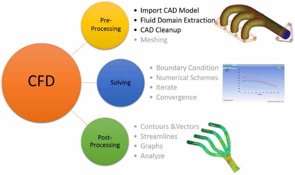
Figure: CFD Process
All meshing algorithms needs a water tight geometry (defined within the constraints of the tolerance considered by meshing software). Creating a clean watertight geometry from dirty CAD is sometimes challenging and in most of the cases very time consuming job.
In this tutorial we are going to learn about ‘Fluid Domain Extraction techniques using ANSYS ICEM CFD. We are going to learn two techniques, one the orthodox way and other the smart way.
Objective of Tutorial
The objective of this tutorial is to show how to extract the fluid domain from the CAD model, using ANSYS ICEM CFD. In order to demonstrate this, a CAD model of an intake manifold will be used in this tutorial. But the same concept can be applied to any manifold geometry or as a matter of fact, any CAD model.
There will be two different methods of cad clean-up explained in this tutorial. First, the orthodox way of extracting fluid domain extraction that involves more manual efforts and time. Second, an alternate way of doing the same with less time and efforts using ‘Subset’ option in ANSYS ICEM CFD.
Please note that this tutorial is focused towards steps involved in CAD cleanup necessary for a CFD analysis that involves only fluid flow and no heat transfer. All the steps right from importing the CAD geometry to creating parts for boundary tagging are covered in this tutorial.
Prerequisite
Following are the prerequisites for using this tutorial:
- Basic understanding of geometric entities like points, curves & surfaces
- Exposure to ANSYS ICEM CFD software interface (GUI)
- Access to ANSYS ICEM CFD software
- We tried to provide detailed explanation about each step. Some of the steps might not include very minor details. It is assumed that you are familiar with ANSYS ICEM CFD and created a mesh for simple CFD geometries
- It is recommended that you have a computer system with 2 GB to 4 GB RAM in order to setup and run this tutorial simulation
- You should have access to PDF file reader to read this PDF file
Benefits of Tutorial
After this tutorial, you should be able to:
- Identify wet surfaces or necessary surfaces to generate mesh for a fluid flow CFD analysis
- Use geometry tools in ANSYS ICEM CFD to extract the fluid domain from the CAD model
- Use ‘subset’ option in ANSYS ICEM CFD to do CAD clean up effectively
- Make dirty CAD model mesh ready
Some Background about CFD Domain
CFD pre-processing, mainly what geometrical details needs to be considered during meshing is strongly governed by what physics one wants to solve for. The same CAD geometry looks different for “only flow solution” and for “flow and heat transfer solution”. So before starting the cleanup and fluid domain extraction work, it’s very important to understand the geometry/device under consideration.
In this tutorial, we are going to extract the fluid domain for intake manifold. So before starting discussing that, let’s first understand what is this manifold? In Fluid Mechanics, a manifold is as a pipe or channel that has several lateral outlets to or from other pipes.
Intake Manifold
In automotive engineering, an intake manifold is the part of an engine that supplies the fuel/air mixture to the cylinders. Once the carburetor, has thoroughly mixed the air and fuel, the said engine mixture passes through the series or manifold of tubes to each of the cylinders.
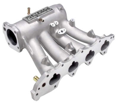
Figure: Intake Manifold
Exhaust Manifold
On the contrary an exhaust manifold collects the exhaust gases from multiple cylinders and deliver it to the exhaust pipe. In a normal engine, once the exhaust gases exit the cylinder they end up in the exhaust manifold and then flow into one pipe toward the catalytic converter and the muffler.

Figure: Exhaust Manifold
Why we do CFD Analysis of Manifold?
Although CFD simulation is not a part of this tutorial, let’s quickly look at why one do CFD analysis of manifold. This will help you to visualize the end outcome from complete CFD analysis process.
Intake Manifold
This auto part is not just a passageway for the mixture to flow into but it also contributes to a better distribution of the fuel and air. The primary function of the intake manifold is to evenly distribute the combustion mixture to each intake port in the cylinder head(s). CFD flow analysis of an intake manifold is performed to check the flow distribution, to optimize the efficiency and performance of the engine.
Exhaust Manifold
The manifold design should make it easier for the engine to push exhaust gases out of the cylinders. This is mainly to decrease flow resistance or back pressure, as increased back pressure levels, the engine has to compress the exhaust gases to a higher pressure which involves additional mechanical work, and can affect intake manifold boost pressure. CFD flow analysis of an exhaust manifold is performed to know the pressure distribution (to reduce back pressure) and velocity distribution at exhaust (main factor behind good scavenging).
Problem Description
An input CAD geometry of manifold is provided. The details of provided geometry is shown in below figure.
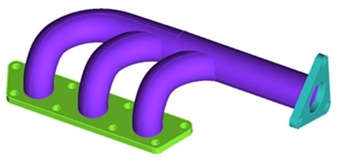
Figure: Manifold CAD Geometry
Assume that the geometry has to be cleaned for CFD analysis. Also assume that the solution is to be done only for flow equations and is without heat transfer. With this assumptions, the objective is to create a watertight geometry with all required parts and their labels.
Tutorial Snippets
These are the few snippets from this tutorial
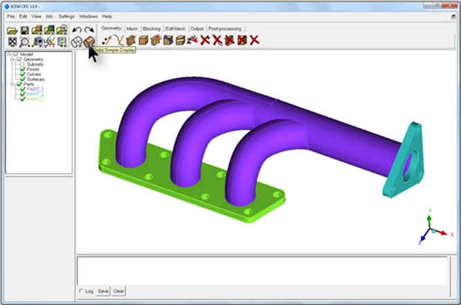
Figure : Imported CAD Geometry
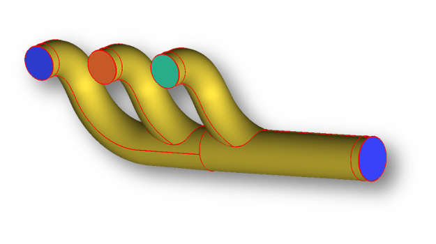
Figure : Extracted CFD Domain
Watch and Follow: Video Tutorial
|
{modal index.php/en/?option=com_content&view=article&id=151|width=800|height=450|title=Fluid Domain Extraction of a Manifold using ANSYS ICEM CFD}
 {/modal} {/modal}
{modal index.php/en/?option=com_content&view=article&id=151|width=800|height=450|title=Fluid Domain Extraction of a Manifold using ANSYS ICEM CFD}
 {/modal} {/modal} |
The Author
{module [327]}