Model Tessellation & Visualization using C++ API in Autodesk Inventor
Autodesk Inventor provides powerful API interface the access the model tessellation and visualization. This blog series attempt to explain how to use Inventor C++ API to get a triangulated geometry from Autodesk Inventor model for downward processing. Assembly document, part document and sheet bodies are covered as model geometry for tessellation. Tessellation data is stored along with feature information and BREP structure in CAD part and assembly file.
Proxy Geometry :
A modern day solid modeling CAD model consist of combination of geometry and topology know as BREP (Boundary Representation) model. Geometry is consist of curves those can be line, circle, ellipse or NURBS curves and surfaces can be consist of Plane, Sphere, Cylinder or generalize NURBS surfaces. Topological entities are connecting, limiting, and space defining entities providing mapping of geometric entities. Feature base modeler have further information of feature definition and dependance. But GPU (Graphics Processing Unit) in your computer can not interpret BREP model. Therefore with every CAD model simplified graphical representation is created called as a tessellation. This tessellation data is stored along with feature information and BREP structure in CAD part and assembly file. Using this data CAD software very quickly show a graphical model in screen without actually going through feature rebuilding process. Because of this reason tessellated geometry is also called as proxy geometry by CAD developers, a fitting name.
Tessellation :
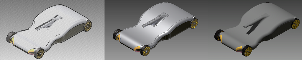
Tessellation is a process of generating segmented polyline from the curve and triangulation from the CAD surfaces. End user always see only graphics representation, tessellation plays an important roll in aesthetic aspect of CAD modeling. If you want to represent a CAD model very accurately using triangles, one may required very large number of triangles. But this may hamper your graphics performance and frame rate update during in zoom, rotation, pan. Therefore good tessellation algorithm always try to generate minimum number of triangles without loosing a geometric information. They are many challenges in tessellation such as bad parametrization, preserving hard edges, incorrectly Trim surface triangulations for tolerant geometric is challenging task.
Autodesk Inventor Customization :
Autodesk Inventor software provides a comprehensive development platform for building special purpose applications for adding new functionality, enhancing existing feature or for performing design automation.
Inventor exposes its programming interface using a COM Automation interface. You can access this interface using most of the popular programming languages available today including Microsoft Visual C++®, VB, C#, and Delphi. Autodesk Inventor C+ interface is one of most powerful interface to perform customization and hence would be used in this blog series.
More than 1000 classes provides these API capability in ordered fashion. Object Model of Inventor API can be accessed from Autodesk website from here.
Getting Tessellation :
Model tessellation can be access in following three steps:
- Identify Document type and access the document
- Collect all the surface bodies from specific document
- Use SurfaceBody.CalculateFacets(...) API to get Triangle List
Following paragraphs would explains these steps with code snippets.
1. Model Document :
The first step is to access model document from inventor application. Inventor Document has four subtype has shown in below figure. Inventor document is nothing but collection of sub objects.
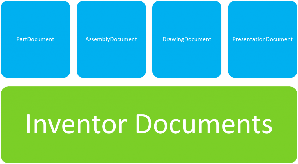
Document types of inventor doc
Using following code one can identify type for inventor document and write a modular code as per document.
if (mApplication->ActiveDocumentType == kPartDocumentObject)
    {
        //write your code here to collect surface bodies from part document.
    }
else if (mApplication->ActiveDocumentType == kAssemblyDocumentObject)
    {
        //write your code here to collect surface bodies from Assembly document.
    }
In above code mApplication is a Inventor Application pointer which one can gets on the loading of your application DLL. From Application pointer we can access active document type.
2. Collecting surfaces bodiesFrom Part Document :
Surface bodies of CAD model can be access from PartDocument using iteration. However part document may contain solid models or sheet models. Surface bodies of of Solid model can be easily access from PartComponentDefinition. But for sheet models, first we need access work surface and from work surface one can get surface bodies. Following code illustrate this concept :
  	vector surfaceBodyList
	HRESULT hr;

	CComPtr	document;
	hr = mInvApplication->get_ActiveDocument(&document);

	CComQIPtr		partDocument(document);
	CComPtr	partCompDef;
	hr = partDocument->get_ComponentDefinition(&partCompDef);

	// Solid bodies
	CComPtrsurfaceBodies;
	hr = partCompDef->get_SurfaceBodies(&surfaceBodies);
	for (int count = 1; count <= surfaceBodies->Count; count++)
	{
		SurfaceBodyPtr surfaceBody;
		surfaceBodies->get_Item(count,&surfaceBody);

		surfaceBodyList.push_back(surfaceBody);

	}

	// Sheet bodies
	CComPtr	workSurfaces;
	hr = partCompDef->get_WorkSurfaces(&workSurfaces);
	for (int index = 1; index <=  workSurfaces->GetCount(); index++)
	{
		CComPtr	workSurface;
		workSurfaces->get_Item(CComVariant( index),&workSurface);
		CComPtr tWorkSurfaceBodies;
 		tWorkSurfaceBodies = workSurface->SurfaceBodies;

		for (int count = 1; count <= tWorkSurfaceBodies->Count; count++)
		{
			SurfaceBodyPtr workSurfaceBody;
			tWorkSurfaceBodies->get_Item(count,&workSurfaceBody);
			surfaceBodyList.push_back(workSurfaceBody);
		}
	}
From assembly document :
Accessing surface bodies from Assembly document is more complicated task. Inventor object proxy are effectively used to represent a entities of part in assembly context without making a copy. An object proxy is a reference to an object through a particular occurrence. Think of it as a pairing with its respective native object, but returns context-specific data.
An example is a face of a part within an assembly. When this face is queried through the API, what do the results mean - are coordinates returned in the context of the assembly, or the native part? What if the part is inserted into the assembly multiple times; how is a particular instance of the face identified? A key purpose of proxies is to provide answers to these questions. In this case, the proxy of the face object performs the necessary transformations to provide point data in the required context, and also provides information about which occurrence the face is associated with.
To the user, the notion of proxies is transparent. When a user selects a part through the Autodesk Inventor user interface, conceptually the part is in the assembly. It doesn't matter to users that they are working with a proxy that is presenting coordinates and faces and so on in the assembly context and not in the context of the referenced part. But developers need to obtain data specifically in the part or assembly context. There is no geometry in the assembly, only a proxy that is performing the required transformations based on the position of the part within the assembly. ComponentOccurances extend the concept of object proxy to assemblies and sub assemblies. Following object model provides the route to access surface bodies from Assembly document.
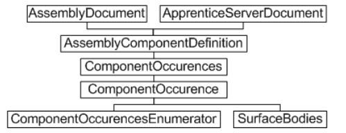 Assembly-level component occurrences and definitions - Object Model Diagram
To simplify the process of accessing surface bodies from assembly lets declare the function getAssemblySurfaceBodies (ComponentOccurrencesPtr, surfaceBodyList). Following code illustrate the usage of the above function.
if(mInvApplication->ActiveDocumentType==kAssemblyDocumentObject)
{
	vector surfaceBodyList
	AssemblyDocumentPtr assmDoc = NULL;
 	assmDoc = (AssemblyDocumentPtr) mInvApplication->ActiveDocument;

	ComponentOccurrencesPtr componentOccurrences = NULL;
	componentOccurrences  = assmDoc->ComponentDefinition->Occurrences;
	hr = getAssemblySurfaceBodie(componentOccurrences,surfaceBodyList);
}
Code checks assembly document type and based on document type either access surface bodies or recursively calls to itself to go further depth of sub assembly. Recursion has helps complex component walkover from root assembly simple.
void getAssemblySurfaceBodies(ComponentOccurrencesPtr inCompOccurrences, vector& outSurfaceBody)
{
  	for (int i = 1; i <= inCompOccurrences->Count; i++)
	{

		ComponentOccurrencePtr compOccurrence = inCompOccurrences->GetItem(i);

		if(compOccurrence->GetSuppressed())
			continue;
		if(!compOccurrence->GetVisible())
			continue;

		// Use the Count property of the SubOccurrences property to determine if it's a subassembly or not.
		ComponentOccurrencesPtr SubOccurrences = compOccurrence->SubOccurrences;

		int SubOccurrencesCount = SubOccurrences->Count;

		if (SubOccurrencesCount > 0)
		{
			// It's a subassembly
			// Recursive call
			getAssemblySurfaceBodies(SubOccurrences,outSurfaceBody);
		}
		else
		{
			// It's not a subassembly
			SurfaceBodiesPtr surfaceBodies = compOccurrence->SurfaceBodies;
			int bodyCount = surfaceBodies->Count;
			for (int count = 1; count <= bodyCount; count++)
			{
				SurfaceBodyPtr surfaceBody = NULL;
				surfaceBody = surfaceBodies->GetItem(count);
				if(surfaceBody == NULL)
					continue;
				if(surfaceBody->GetVisible()){
					outSurfaceBody.push_back(surfaceBody);
					surfaceBodyMatrix.push_back(NULL);
				}
			}

			ComponentDefinitionPtr componentDefinitionPtr;
			componentDefinitionPtr = compOccurrence->GetDefinition();

			ObjectTypeEnum objEnum = componentDefinitionPtr->GetType();
			if(objEnum == kPartComponentDefinitionObject)
			{
				matrix = compOccurrence->GetTransformation();
				// Surface bodies Triangulation
				CComPtr	workSurfaces;
				PartComponentDefinitionPtr partComponentDefinition(componentDefinitionPtr);
				hr = partComponentDefinition->get_WorkSurfaces(&workSurfaces);
				for (int index = 1; index <=  workSurfaces->GetCount(); index++)
				{
					CComPtr	workSurface;
					workSurfaces->get_Item(CComVariant( index),&workSurface);
					CComPtr tWorkSurfaceBodies = workSurface->SurfaceBodies;

					for (int count = 1; count <= tWorkSurfaceBodies->Count; count++)
					{
						SurfaceBodyPtr workSurfaceBody;
						tWorkSurfaceBodies->get_Item(count,&workSurfaceBody);
						if(workSurfaceBody->GetVisible())
						{
							outSurfaceBody.push_back(workSurfaceBody);
						}
					}
				}
			}
			else if(objEnum == kSheetMetalComponentDefinitionObject)
			{
				// Surface bodies Triangulation
				SheetMetalComponentDefinitionPtr SheetMetalComDef(componentDefinitionPtr);
				CComPtr	workSurfaces;
				hr = SheetMetalComDef->get_WorkSurfaces(&workSurfaces);
				for (int index = 1; index <=  workSurfaces->GetCount(); index++)
				{
					CComPtr	workSurface;
					workSurfaces->get_Item(CComVariant( index),&workSurface);
					CComPtr tWorkSurfaceBodies = workSurface->SurfaceBodies;

					for (int count = 1; count <= tWorkSurfaceBodies->Count; count++)
					{
						SurfaceBodyPtr workSurfaceBody;
						tWorkSurfaceBodies->get_Item(count,&workSurfaceBody);
						if(workSurfaceBody->GetVisible())
						{
							outSurfaceBody.push_back(workSurfaceBody);
						}
					}
				}
			}
		}
	}
}
3. Getting the the tessellation form Surface bodies :
This is a final step. Once you have list of surface bodies you have to just ask for facet inform from surface. GetExistingFacets API on SurfaceBodies gives you the existing facet stored by inventor. This is a fast API as no extra computation is done by Inventor and with low memory footprint as data is single precision. However if you need a more accurate tessellation as per your tolerance and with latest feature change you can use CalculateFacets API on SurfaceBodies. Following snipet provides you code syntax and variable description :SurfaceBody.CalculateFacets(double Tolerance, long* VertexCount, long* FacetCount , SAFEARRAY** VertexCoordinates, SAFEARRAY** NormalVectors, SAFEARRAY** VertexIndices)
a) Tolerance : Input Double that specifies the maximum distance that the facet can deviate from the smooth surface. This value is in centimeters. Smaller values can result in a much greater number of facets being returned and will require more processing time to calculate.
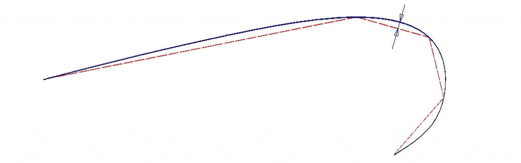
- Tessellation Tolerance
b) VertexCount : It represents output Long that returns the number of vertices that were generated.
c) FacetCount : It represents output Long that returns the number of facets that were generated.
d) VertexCoordinates : It represents output array of Doubles that contains the coordinate locations of the vertices.
e) NormalVectors : It represents output array of Doubles that defines the normal for each vertex in the facet mesh.
f) VertexIndices : It represents output array of Longs that are used as index values to index into the vertex coordinate list.
If you wish to change the existing tolerance, first calculate the existing tolerance using GetExistingFacetTolerances() API and then use the best tolerance to calculate facet. Following code demonstrate how to access triangulation from Surface Body.
void getFacetFromSurfaceBodies( const vector& inSurfaceBody)
{

	HRESULT hr = S_OK;

	vector	arrVertex;
	vector		arrIndex;

	int currIndex=0;
	for(int i=0;i<inSurfaceBody.size();i++)
	{

		SurfaceBodyPtr surfaceBody = inSurfaceBody[i];

		//Determine the highest tolerance of the existing facet sets.
		long toleranceCount;
		SAFEARRAY* existingTol =NULL ;
		double* pTols;
		surfaceBody->GetExistingFacetTolerances(&toleranceCount,&existingTol);
		long index = 0;
		double bestTol=0.1;
		hr = SafeArrayGetElement(existingTol,&index,&bestTol);
		for (long i = 1; i < toleranceCount; i++)
		{
			double tol;
			hr = SafeArrayGetElement(existingTol,&i,&tol);
			if (tol < bestTol)
				bestTol = tol;
		}

		//Get a set of existing facets.
		long vertexCount;
		long facetCount;

		//Calculate Facets on each Surface Body
		SAFEARRAY* vertexCoords = NULL;
		SAFEARRAY* normalVectors = NULL;
		SAFEARRAY* vertexIndices = NULL;
		hr=surfaceBody->CalculateFacets(bestTol,&vertexCount,&facetCount,
			&vertexCoords,&normalVectors,&vertexIndices);
		int length;
		long lBound;
		long uBound;
 		unsigned int dim = SafeArrayGetDim(vertexCoords);
		hr = SafeArrayGetLBound(vertexCoords,dim,&lBound);
		hr = SafeArrayGetUBound(vertexCoords,dim,&uBound);
		length = (uBound - lBound)+1;

		size_t lastVSize = arrVertex.size();
		arrVertex.resize(lastVSize+length);

		//Get x,y,z coordinate of each vertex
		float x,y,z;
		for(long i=0;i<length;i+=3)
		{
			SafeArrayGetElement(vertexCoords,&i,&x);
			arrVertex[lastVSize+i] = x;
			i++;
			SafeArrayGetElement(vertexCoords,&i,&y);
			arrVertex[lastVSize+i] = y;
			i++;
			SafeArrayGetElement(vertexCoords,&i,&z);
			arrVertex[lastVSize+i] = z;
		}

		//Get indices from index array to create facet
		lastVSize = arrIndex.size();
		arrIndex.resize(lastVSize+ (facetCount*3));
		for(long i=0;i<facetCount*3;i++)
		{
			int val;
			SafeArrayGetElement(vertexIndices,&i,&val);
			arrIndex[lastVSize+i] = currIndex + val-1;
		}
		currIndex = arrVertex.size()/3;
	}
	return S_OK;
}
We hope you enjoyed reading the blog with better understanding of model tessellation in Inventor. Write your questions, queries and suggestion. In next part of blog we will elaborate how to display this tessellated geometry in Autodesk Inventor using transient geometry feature of Inventor.
The Author
{module [313]}