Using UDF for CFD Modeling of Boiling Phenomena
Having the basic introduction to writing a UDF from the earlier article "Writing a UDF for CFD Modeling" wherein we saw using UDF for inserting custom boundary profiles, we shall now see another application of UDF with an example of boiling phenomenon. To get the most understanding from the current article the reader should be familiar with ANSYS Fluent software and basic UDF understanding.
Also the reader is recommended to go through the article "Mathematical Treatments in CFD Modeling of Multiphase Flows" along with the above mentioned.
The Boiling phenomenon :
Boiling is probably the most familiar form of heat transfer, yet remains to be the least understood. Although a wide number of research papers are available on the subject yet we do not completely understand the exact process of bubble formation and still rely on empirical or semi-empirical relations to predict the rate of heat transfer through boiling.
Boiling is a convection process involving a change in phase from liquid to vapor occurring when a liquid is in contact with a surface maintained at a temperature higher than the saturation temperature of the liquid.
Why study Boiling ?
Many engineering applications involve boiling heat transfer, for example in steam power plant, heat is transferred to steam in boiler where water is vaporized. In the household refrigerator, the refrigerant absorbs heat from the refrigerated space by the boiling process within the evaporator section. The phenomenon of boiling heat transfer has also been successfully used in the cooling of nuclear reactors and rocket engines where energy dissipation rates are extremely large and thus there are many wide range of applications in which boiling phenomenon plays an important role.
Classification of Boiling :
Boiling is classified as:
- Pool boiling : If heat added to a liquid from a submerged solid surface, the boiling process is referred to as pool boiling. In this process the vapour produced may form bubbles, which grow and subsequently detach themselves from the surface, rising to the free surface due to buoyancy effects. e.g. boiling of water in kettle on a stove.
- Flow boiling : Flow boiling occurs in a flowing stream and the boiling surface may itself be a portion of the flow passage. This phenomenon is generally associated with two phase flows through a confined passage.
Boiling regimes
If temperature of surface is {tex} T_S {/tex} and saturation temperature of liquid is {tex} T_{SAT} {/tex}, then {tex} T_S- T_{SAT} = \Delta T_E {/tex}, the excess temperature.
Depending on values of excess temperature, four different regimes are observed.
- Free convection zone : In this zone excess temperature is very small. Here liquid layer next to the hot surface is slightly superheated. The convection currents circulate the liquid and evaporation takes place at liquid surface.
- Nucleate boiling : In this region excess temperature is higher than that of free convection zone. As the excess temperature is increased, bubbles begin to form on the surface. If we further increase excess temperature, bubbles are formed more rapidly and rise to the surface of the liquid resulting in rapid evaporation. As the excess temperature goes on increasing heat flux also increases upto a maximum value known as critical heat flux. Nucleate boiling regime exists up to critical heat flux only, next regime is film boiling regime.
- Film boiling : After reaching critical heat flux value, heat flux decreases with further increase in temperature. This is due to the fact that bubbles are now formed so rapidly that they blanket the heating surface with a vapour film preventing the inflow of fresh liquid from taking their place. Now this heat must be transferred through this vapour film (by conduction) to the liquid for carrying out any further boiling. Since the thermal conductivity of vapour film is much less than that of the liquid, the value of heat flux must then decrease with increase of excess temperature. If we keep on increasing the excess temperature up to a certain limit, the vapour film remains unstable. Later the vapour film stabilizes with further increase in temperature and the heating surface is completely covered by a vapour blanket. With this the heat flux further reduces reaching its lowest value. The surface temperature required to maintain a stable film is high and under these conditions a sizeable amount of heat is lost by the surface due to radiation.
The phenomenon of stable film boiling can be observed when a drop of water falls on a red hot stove. The drop does not evaporate immediately but dances a few times on the stove. This is due to the formation of a stable steam film at the interfaces between the hot surface and liquid droplet. Below is a visual demonstration for a water drop boiling on a hot stove.
http://www.youtube.com/watch?v=j11kNL6Kg0s
(Source: youtube)
Heat transfer rates and excess temperatures associated with nucleate boiling are small. The equipment used for boiling should be designed to operate in this region only. Now having had a overview of the physics of boiling, let us see how UDF can be applied to model film boiling.
Why we need UDF for Boiling type of simulations ?
In this simulation there are two distinct phases liquid and gas, so this simulation has to be solved using multiphase flows. In boiling, flow is separated where a distinct interface is present between liquid and gas, so it is advised to use VOF (volume of fluid) model for such flows. VOF uses Eulerian framework for both phases with specialized interface treatment. The boiling simulation will include mass transfer between two phases. As we know that VOF model doesn’t simulate mass transfer mechanism, UDF comes into picture for performing this additional task.
Compiling the UDF :
We can either compile UDF or interpret it. In this demonstration of simulation of boiling we shall choose compilation method. Complied UDF is nothing but code written in ‘C’ language and translated in machine language (language understood by computer) and the UDF becomes part of native fluent software. As we need to compile the UDF, we require a compiler. Few of the supported compiler for ANSYS Fluent are, Microsoft Visual Studio or the Express editions. The point to be noted here is one needs to start Fluent from command prompt of visual studio environment.
Test Case :
The geometry of a column is represented in the following figure with it's domain filled by fluid. The bottom wall is maintained at 10 K above saturation temperature of the fluid and at top (pressure outlet) there is saturation temperature at atmospheric pressure.
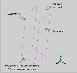
Geometry and boundary conditions
How to add mass transfer mechanism in our UDF :
To add mass transfer mechanism in our UDF we need to add it as a source term using macro DEFINE_SOURCE(). We will need 2 'source terms', one for gas and one for liquid as follows:
Defining source term for gas : DEFINE_SOURCE(gas, cell, thread, dS, eqn)
Defining source term for liquid : DEFINE_SOURCE(liquid, cell, thread, dS, eqn)
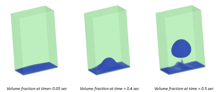
Results :
Thus the results obtained below shows the successful CFD simulation of film boiling process. The images show the bubble formation with respect to time. As can be seen at time 0.05 sec the film layer had developed completely followed by the bubble formation at the centre of the column (i.e. bottom wall) as time advances to 0.4 sec and complete bubble detachment at 0.5 sec, completing the boiling cycle. The video further gives insights of the phenomena and seems to match the real life behavior of film regime boiling process.
|
{modal index.php/en/?option=com_content&view=article&id=130}
 {/modal} {/modal}
{modal index.php/en/?option=com_content&view=article&id=130}
 {/modal} {/modal} |
References :
1. www.ansys.com
2. Introduction to Heat Transfer; Frank P. Incropera, David P. DeWitt
The Author
{module [312]}