Recent Trends in Modeling of Combustion
Computational fluid dynamics (CFD) when saw its development on the peak, was meant to merely validate simulations with the experimental results. But the recent trends have shown that confidence in CFD has grown and its use is on the rise to simulate physics problems which have very limited experimental data for its validation. Combustion is one such field where application of CFD and this recent trend has proved to be a boon.
A genre of sophisticated codes for modelling combustion phenomenon has been developed in the last few decades. The challenges faced by engineers and developers is to develop such codes that will represent “perfectly” the observed temperature and concentration profile and to use this codes or models to further simulate and predict the events where no measurements are possible or no data is available. The reader is expected to already have some exposure about CFD modeling and its understanding before proceeding with this article.
To model combustion, the information related to the fluid mechanics of the system must be known. All the transport phenomena such as convection, diffusion as well heat should be accurately incorporated in such models. Chemical reaction schemes must also be known so as to estimate the formation of combustion products and species and also to predict ignition, stabilization and extinction of flames. Radiation also takes place due to presence of soot formed during combustion and also there is radiative heat transfer from wall of the combustion chamber. Combustion of fuels comes under multiphase system, where liquid fuels is a two phase system consisting of liquid and gas phases while solid fuel belongs to a three phase system. The challenges faced are to model breaking up of the liquid fuel, its reaction and distribution of the reactants in three dimensional spatial systems. These models which form part of CFD, has become an indispensable tool for combustion modelling.
Before we begin a detailed review of CFD applied to combustion phenomenon a few points to note for beginners to CFD :
- CFD finds its application in sciences involving fluid dynamics.
- Prediction of heat transfer, mass transfer, chemical reactions are carried out by solving governing equations.
- The programs or the models use finite volume methods to solve the Navier-Stokes equations & energy equations.
CFD for combustion in power plant
CFD modelling is used to simulate the combustion of coal in boilers of power plants. Coal undergoes pyrolysis, followed by combustion of coke. Hence the accuracy of the result depends on the sub-models chosen for devolatalisation, char combustion and soot formation. Also heat transfer models and turbulence model, if chosen accurately gives reasonable results. As turbulence affects the heat transfer and chemical processes occurring in pulverised coal boiler, three dimensional flow field is assumed. The transport property of solid fuel is different than the gas surrounding it. Hence for simulation, they are generally modeled as it is and then coupled using a source term in transport equation. Radiation and turbulence find dependence on one another in combustion CFD. Radiation effects come into picture due to fluctuation of temperature and species concentration which are in turn affected due to turbulence. This links up turbulence with radiation.
Below are some of the areas where CFD finds direct application within power plant industry :
- Coal burning and combustion analysis.
- NOx burner design and analysis of its effect on combustion and thermal performance.
- Draft loss and ductwork analysis
- Coal flow distribution, improvement in pulverizer performance, and reduce coal pipe and burner head erosion.
- Analysis of gas flows in a furnace
- Design of emission control systems for coal-fired power plants (NOx, SOx, mercury, CO2)
- Design of thermal and fluid problems of nuclear reactors
- Efficiency improvements for turbines
- Design of combustion and power generation equipments
- Modeling of vibration, fatigue and thermal stress in welded components, piping systems, connections, tanks, reactors and pressure vessels
- Design of wind power systems including turbine blades, components, electronic systems and towers.
- Development of solar collection panels and storage systems
- Design of hydropower plants and surrounding waterways
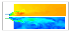 Velocity and temperature profile at bottom and top respectively
(Image source: Combustion modelling opportunities and challenges for oxy-coal carbon capture technology P. Edgea, M. Gharebaghia, R. Ironsb, R. Porter, R.T.J. Porter, M. Pourkashaniana, D. Smithc, P. Stephensond, A. Williamsa)
The article DEVELOPMENT OF THE ADVANCED SIMULATOR FOR FLY ASH MODIFICATION IN THE PULVERIZED COAL COMBUSTION FURNACE describes simulation approach to model fly ash modification behavior by direct injection of Ca fine particles in coal combustion furnaces. Also the Role of Engineering Simulation in Clean Coal Technologies is a nice article on application of CFD to come up with clean technology solutions for power industry.
Combustion modeling in CFD from safety point of view
Hydrogen, as a fuel has found its application as a clean source of energy. Hydrogen being a light gas has high transport properties such as thermal conductivity, diffusion coefficient and has wide range of flammability limits. Hydrogen which is used in light water reactor in nuclear power plant when undergoes combustion, results in high pressure loads acting on the container. The pressure loads are a function of the turbulent flame speed. This is where CFD is applied to predict the pressure loads accurately. For this, hydrogen deflagration and its various regimes are identified. While resolving combustion, in which turbulence plays a vital role, the accuracy of the results largely depend on the mesh size and the time step resolution, as well as, on the initial turbulence conditions. This initial turbulence conditions are measured from the experiments which are used to validate the CFD result. Resolving the turbulent flame thickness by the mesh size helps in predicting the results accurately.
Below are some of the application areas :
- CFD has application in safety systems designs in below areas :
- Hydrogen Management
- Boron Dilution Transients
- Pressurized Thermal Shock
- Thermal Fatigue
- Air and water pollution control equipment
- Recycling and waste management systems
- Chillers, scrubbers and spray towers
CFD analysis of a combustion chamber to model fluid flow
Combustion taking place in a combustion chamber is accompanied with high amount of turbulence. To simulate the piston motion, dynamic mesh is used i.e the mesh generation approach can be used to treat the moving piston as a moving solid body in the computational domain without generating new meshes every time at each crank angle. The finite volume method can accommodate any type of grid. Thus, it is suitable for complex geometries. This fluid flow can be simulated and visualized along with temperature distribution in the combustion chamber.
Below are some of the application areas of CFD within combustion systems :
- Intake systems
- Ports
- In-cylinder flow and combustion
- Engine block, head, components
- Exhaust and after-treatment
- Fuel supply
- Engine ancillaries
- Improvement of burner configurations in industrial furnaces
- Reduction of NOx emissions from petroleum refineries
- Investigation of novel clean energy technologies
- Prediction of CO emission rates
- Model and minimize thermal stresses in combustion equipment
- Reduction of soot formation in furnaces
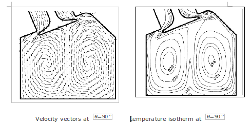
Fluid flow profile and temperature distribution inside a pent-roof type combustion chamber
(Image source: CFD modeling of heat transfer and fluid flow inside a pent-roof type combustion chamber using dynamic model; Yasin Varol, Hakan F. Oztop, Mujdat Firat, Ahmet Koca)
The article Simulation of Flow and Combustion in Internal Combustion Engines describes modeling approach for flow and combustion within an IC engine.
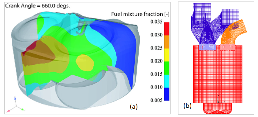
(a) Fuel mixture distribution in a combustion chamber of HCCI engine (b) Computational mesh of an engine
(Image source- Mixing models for the two-way-coupling of CFD codes and zero-dimensional multi-zone codes to model HCCI combustion H. Barths, C. Felsch, N. Peters)
Simulation of spray flames
In space shuttle engines, the combustion chamber has many individual elements which are used to inject fuel and oxidizer in the high pressure chamber. The degree of mixing and the extent of combustion determines the thrust generated. These conditions therefore need to be known accurately. Also practical simulation of these space shuttles is not possible. Hence engineers have largely become dependent on CFD. The distribution of droplets as well as the particle size in the combustion chamber cannot be measured due to presence of many injector elements. Hence investigators have used a simplified way of assuming the fuel to exist in gaseous state, which is sensible as the fuel droplet would enter and evaporate instantly at such high pressures and temperatures. The new spray flame model is computationally efficient for three-dimensional injector flow field simulations.
An interesting article about premixed combustion modeling is provided at the link: PROGRESS IN THE SELF-SIMILAR TURBULENT FLAME PREMIXED COMBUSTION MODEL
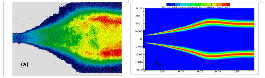 (a) Time averaged emission of OH concentrations (b) OH concentration in a Rocket combustion modelling test case
(Image source- CFD analyses of complex flows, Richard Farmer, Ralph Pike, Gary Cheng)
To summarize this article, we have seen the different areas where combustion modeling is applied as a design tool to come up with new designs within various industries. We also discussed different challenges that one encounters an engineer while applying CFD for simulating combustion. We also reviewed the progress in development of new models for combustion simulation and hope the article threw some light on highlights of combustion modeling and its application within industry.
References :
- CFD analyses of complex flows - Richard Farmer, Ralph Pike, Gary Cheng
- CFD modeling of heat transfer and fluid flow inside a pent-roof type combustion chamber using dynamic model - Yasin Varol, Hakan F. Oztop, Mujdat Firat, Ahmet Koca
- Combustion modelling opportunities and challenges for oxy-coal carbon capture technology P. Edgea, M. Gharebaghi, R. Ironsb, R. Porter, R.T.J. Porter, M. Pourkashanian, D. Smith, P. Stephenson, A. Williams
- The role of CFD combustion modeling in hydrogen safety management—Part I: Validation based on small scale experiments Pratap Sathiah, Ed Komen, Dirk Roekaerts
- Mixing models for the two-way-coupling of CFD codes and zero-dimensional multi-zone codes to model HCCI combustion H. Barths, C. Felsch, N. Peters
- Effect of fuel injection timing and intake pressure on the performance of a DI diesel engine – A parametric study using CFD B. Jayashankara, V. Ganesan
- www.ansys.com
- www.cd-adapco.com
The Author
{module [317]}