Multiphase Flow Modelling of Fuel Tank Sloshing
Having already gone through the earlier blogs particularly, Multiphase Flow Modeling using CFD wherein we discussed about multiphase flow physics i.e. What is a multiphase flow? What are its classifications ? and Mathematical Treatments in CFD Modeling of Multiphase Flows where we explained about the different mathematical modeling approaches and differences between them.
Now talking about an industrial application of multiphase flow we shall discuss about fuel tank sloshing as a test case.
Tank sloshing occurs when a tank filled with either fuel or any fluid is subjected to external excitation forces. Typical examples are ships with large ballast tanks and liquid cargo carriers (e.g. oil tankers) that are often at risk of exposure to sloshing loads during their operational life. Although inserting baffles and similar structural objects damps the sloshing movement intensity of liquid fuel, however cannot be used for fuels like liquefied natural gas (LNG) carriers and thus sloshing has evolved as a main design constraint wherein the accurate calculation of the sloshing loads becomes an essential element of tank design process for safe transport of fuels.
Test Case Name : Fuel Tank Sloshing
Domain Application : Oil & Gas, Automobile, Aerospace
Physics : Transient Multi-Phase Flow with Free Surface
Software Tools Used :
Pre-Processing : ANSYS ICEM-CFD 13.0
Solution : ANSYS FLUENT 13.0
Post-Processing : ANSYS FLUENT 13.0
Objective : Two objectives were set for the present study :
1. To investigate the free surface movement of liquid fuel in a tank under varying acceleration scenarios
2. To compare the effects of baffles (anti-wave baffles) on intensity of sloshing.
Problem Physics : Wherever we have tanks containing bulk volumes of liquid fuel and there is a change in acceleration of the vehicle carrying the tanks there is sloshing. The occurrence of sloshing is basically a two-phase flow between the air and the liquid fuel present in the volume. Depending upon the applications and where the tank is located, sloshing can pose challenges for the structural design or safe transportation of the fuel.
In real life scenarios such phenomenon is applicable for :
1. In automobile fuel tank, to investigate and ensure the continuous supply through fuel pick-up line and
2. In oil & gas companies, to investigate the effect of ship motion of sloshing of oil in production separator/ oil surge vessel/ hydrocarbon storage tank.
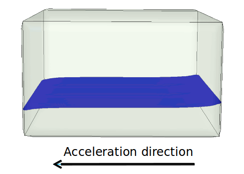
We take a case of a tank half filled with kerosene fuel on a vehicle. The vehicle undergoes acceleration in the positive X-axis direction of 9.81 m/s2 for 1.5 seconds and then the acceleration stops for the next 1 sec. In the state the tank is under the influence of gravitational force for all the time as shown in image below.
We shall solve the demonstration for three cases :
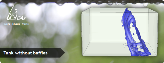
Case 1. Tank without baffles
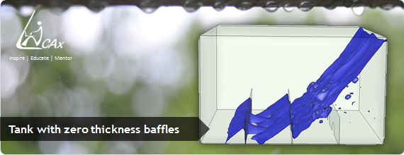
Case 2. Tank with zero thickness baffles. The baffles have semi-circular holes, two on each baffle.
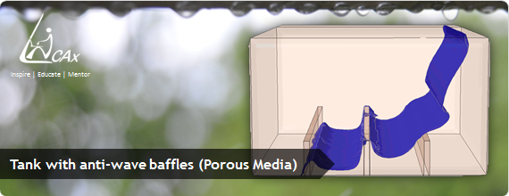
Case 3. Tank with porous baffles, having an array of holes.
Physically as it is very complex and computationally very expensive to model them as they are, hence we approximate these perforated baffles into porous media with some thickness with the same overall effect, as shown in figure below. The purpose of baffles is to damp the oscillation/ sloshing to provide structural stability.Below images shows the distinguishing factors for the geometries we have used for each case.
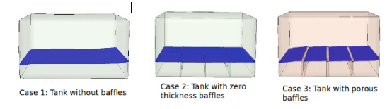
Three cases under study
Details of case set-up :
- Primary phase: Air
- Secondary phase: Kerosene
- Distinct free surface between two phases
- Flow Physics : Transient, porous media
Transient Behavior :
- Total cycle time: 2.5 sec
- Acceleration of 9.81 m/s2 in positive x-direction for 1.5 sec
- Acceleration of 0 m/s for 1.5 to 2.5 sec
- Gravitational force acting all the time
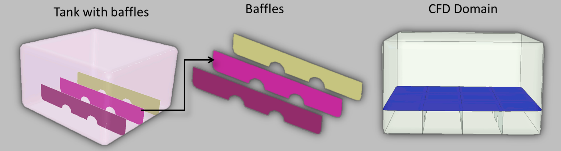
Case-2: Baffles with zero thickness
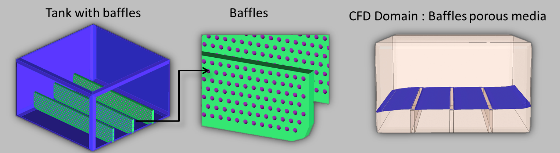
Case-3: Baffles with thickness & porosity
Simulation results for the three cases
Tanks sloshing animation for three cases :
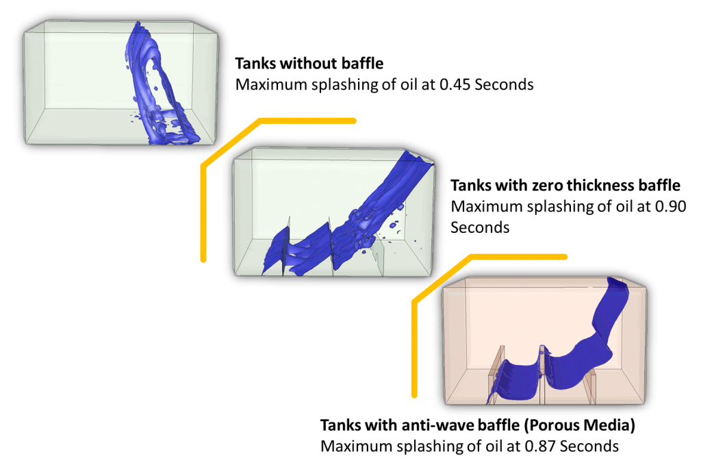
Case 1 : Maximum splashing of kerosene occurs at 0.45 second, i.e. quite early. The volume of fluid (VOF) model was used to solve the case.
|
{modal index.php/en/?option=com_content&view=article&id=132}
 {/modal} {/modal}
{modal index.php/en/?option=com_content&view=article&id=132}
 {/modal} {/modal} |
Case 2 : Splashing occurred at 0.9 second. As can be seen the splashing intensity is reduced because of the presence of baffles and settlement of the fluid (kerosene) is more quicker as compared to in Case 1, as the splashing is damped with the baffles.
|
{modal index.php/en/?option=com_content&view=article&id=133}
 {/modal} {/modal}
{modal index.php/en/?option=com_content&view=article&id=133}
{/modal} |
Case 3 : Splashing occurred at 0.87 second. Here we have baffles with thickness and porosity and hence the damping is more as compared to the earlier cases. Thus kerosene settles down pretty faster also as can be seen the animation below.
|
{modal index.php/en/?option=com_content&view=article&id=134}
 {/modal} {/modal}
{modal index.php/en/?option=com_content&view=article&id=134}
{/modal} |
This demonstrates application of VOF multiphase flow model to carry out sloshing simulation studies. As CFD clearly shows the intensity of sloshing as a function of time, CFD simulations can serve as an important tool to tackle such industrial problems of tank sloshing providing detail insights for design optimization.
The Author
{module [311]}