Grid Generation for CFD Simulation : Introduction
After a brief introduction to computational fluid dynamics (CFD) in the earlier blog Introduction to CFD, let-us further try to understand and have greater insights into the meshing process in the pre-processing step of CFD simulations.
Simulation is a broad subject area that is currently used to analyse or design products and processes. Within simulations we can analyse different aspects like structural, as well as thermal and fluid flow analysis, however the basis for all simulation softwares and studies is the mesh, also called a grid.
So before we start any simulation study to get any result the first step followed is creating a mesh or a CFD CAD model. Therefore meshing is an extremely critical part of CFD process and without understanding it we cannot proceed to solve or even expect any relevant results. Also the accuracy of the CFD simulation results is directly linked to meshing. the better the mesh in quality, the more accurate results can be expected. Almost 50% of the CFD simulation time of any CFD engineer is involved into meshing or mesh generation and hence it is a critical part of the CFD simulation process that needs thorough understanding of the meshing/ grid generation steps.
The CFD Simulation Process :
Pre-processing : Mesh generation is a combination of CAD model generation as well as CAD clean-up and termed as pre-processing in the entire CFD simulation process. Pre-processing means, before we move ahead to the solver we need to process CAD model in order to fit into the solver or provide the solver with the correct information.
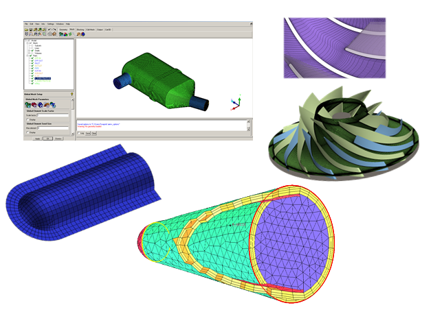
Within pre-processing we create the geometry, and perform clean-up so that unwanted parts if any are deleted or modified. We generate the mesh, & specify the boundary conditions (B.C), then this entire meshed CAD model is exported to a CFD solver along with B.C. A few CAD models are shown below with their meshing.
Solver : In the solver we import the meshed CAD model and solve the CFD problem specifying additional models like the physics, numerical computation methods etc.
Post-processing : Extracting results out of the CFD model that has been solved, is called as post-processing. Here we analyze and try to understand the results using various color, contour plots, lines, contour data, graphs etc. We can extract data like heat transfer coefficient, drag, lift in the analysis of product design and generate good analysis report.
For more details about the CFD simulation process please refer to : Understanding CFD Simulation Process with Examples
Mesh Generation :
Mesh or grid is defined as a discrete cell or elements into which the domain/ model is divided. All the flow variables & any other variables are solved at centres of these discrete cells. This entire process of breaking up a physical domain into smaller sub-domains (elements/ cells) is called as mesh generation.
Why we need a Mesh ?
Basically a mesh is required because by physics or mathematical theory we are solving the variables like flow and heat transfer and any other variable at these cell centres or nodes. Also the theoretical methods that are used for any CFD study like the fine difference method (FDM), finite element method (FEM) and the finite volume method (FVM) actually solve the variable at these discrete cells/ nodes.
There are different types of grid/ cell shapes e.g. triangles, quadrilateral, tetrahedra, hexahedra etc, that will we shall see in detail. for e.g. the image below shows a glimpse of a CFD random mesh between two circles, the domain of analysis. We have filled the space (torus) by many small triangles called as cells or elements. A grid or mesh is a collection of all these triangles.
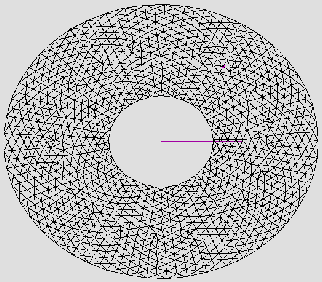
Here the point that needs to be noted is that the mesh composed of many triangles are always connected with each other, however they never intersect with each other.
The domain inputs that would be needed for solving the equation are:
- Appropriate shape & size of domain in which the equation will be solved.
- The domain needs to be discretized as it will be given to the solver for solving equation in discretized form.
- Domain & boundary tags (boundary conditions); making sense of physics.
- Write output file needed for the solver.
Below shows a pre-processing example of a fin-tube heat exchanger.
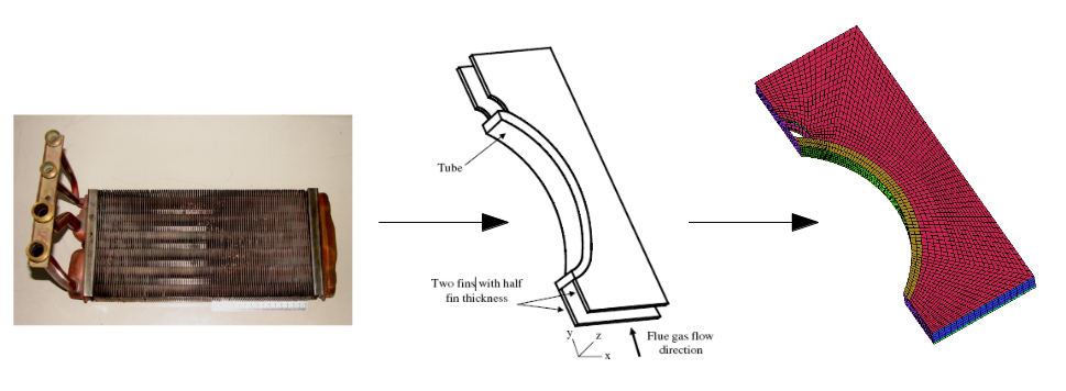 Meshing of a fin tube heat exchanger
The typical steps involved during pre-processing can be summarized as:
- Creating the shape & size of domain, generally supplied through CAD data.
- Standard CAD software – Used for complex geometries and involves repair operation as the result of import/export issues.
- Pre-processing tool like ANSYS ICEM-CFD – For simple geometries. Almost negligible repair operation.
- Dividing the domain in small cells - Also called as mesh generation, grid generation, domain discretization.
- Various methods like structured multiblock, Cartesian, unstructured methods
- Putting tags on the boundaries and domain
- Boundary or surface tags – Inlet, outlet, wall etc.
- Domain tags – Solid, fluid etc.
- Exporting mesh to various solver
- Writing the mesh in specific solver format
Meshing Terminologies :
- Cells & element types : The cells & elements shapes should be supported by the used solver. Typical cell shapes supported by commercial solvers (ANSYS Fluent, ANSYS CFX) are of following types:
- For 2-D & 3-D elements :
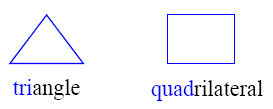
2D Elements
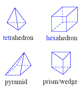
3D Elements
Pre-processing software, ANSYS ICEM CFD :
ANSYS ICEM CFD is a complete and standalone preprocessing software. We can do CAD model creation, CAD repair as well as mesh generation within ICEM CFD. Typical tasks that CFD engineer performs is:
- Geometry creation
- Import repair
- Mesh generation
- Multiblock Structure Hexa
- Unstructured hexahedral
- Unstructured tetra
- Cartesian with H-grid refinement
- Hybrid meshes
- Quadrilateral and triangular surface meshes
- Boundary conditions
- Creating tags for boundary conditions
- Exporting mesh
- Exporting mesh for different solvers
A typical GUI of ANSYS ICEM CFD is as shown in figure below :
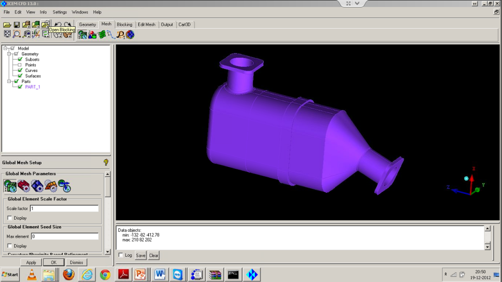
Graphic User Interface (GUI) of a commercial preprocessor, ANSYS ICEM CFD
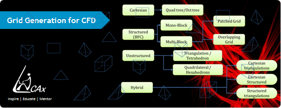
Types of Grid / Mesh :
The typical types of grid/ mesh used for a commercial software for academic or industrial applications are:
- Cartesian
- Structured
- Unstructured
- Hybrid
The mesh generally may not always consist of a single type of elements viz., triangles or rectangular blocks etc. Sometimes we need to use different meshing techniques to shape the model in order to capture the shape of a particular CAD model. The mesh elements therefore at the same time may consist of cartesian, structured, unstructured & hybrid mesh. Within structured grid we have mono-block & multi-block type of mesh. Mono-block & multi-block meshing are the processes we follow to get a structured type of mesh. Within unstructured grid, we have triangular tetrahedron & with Hybrid grid we have a mix of above discussed elements.
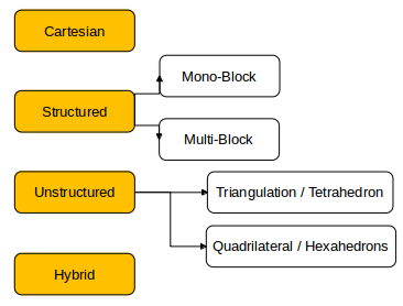 Types & classification of grid/ mesh
1. Cartesian Grid :
Cartesian grid means that the entire set of discrete cells that we will be using in order to fill the CFD space are aligned along the orthogonal axis, i.e. alignment along the x, y & z axis. eg. as below :
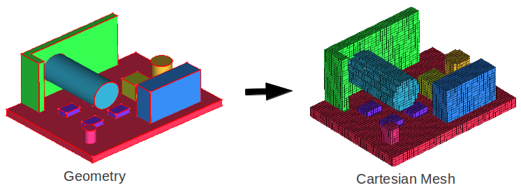 Cartesian mesh generation example
This facilitates the use of square or rectangles/ cubes, the most simple form of mesh but it does not capture the shape exactly & hence used rarely. Also the result obtained with this will not be that accurate & typically used for very simple type of geometries.
2. Structured Grid :
Here a single block is used to cover the entire geometry. Also used for simple shapes, where a single block is sufficient for covering the CAD model.
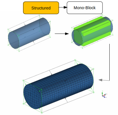 Structured grid generation of a cylinder using mono-block
In a Structured Mesh, elements are aligned in a specific manner or they follow a structured pattern & hence the name structured mesh. Conversely, if the elements are arranged in a random fashion or haphazardly they are called un-structured mesh.
Structured Mono-Block Grid :
For preparing a structured mesh a single bounding block is used to cover the entire geometry. Also used for simple shapes where a single block is sufficient for actually covering the entire CAD model.
In order to generate mesh for the cylinder (example below) we can cover the cylinder with a bounding box that can be a single bounding box & then generate the mesh for entire cylinder, called a mono-block since a single bounding block is used for generating mesh.
Structured Multi-Block Grid :
Within structured mesh the other method we use to mesh a complex geometry is called a multi-block. Let us say, if suppose in the core of cylinder we want to generate a finer mesh or a different pattern compared to the outer region, thus to seperate this we at times use more than one bounding box (figure below). Similarly for a complex geometry like the catalytic converter, we cannot cover the shape by a single bounding box so we generate diffrent bounding box for diffrent shapes within the same CFD space & then combining these blocks we make a single structured mesh. Since there are multiple blocks involved in the mesh generation process this is called multi-block structured mesh.
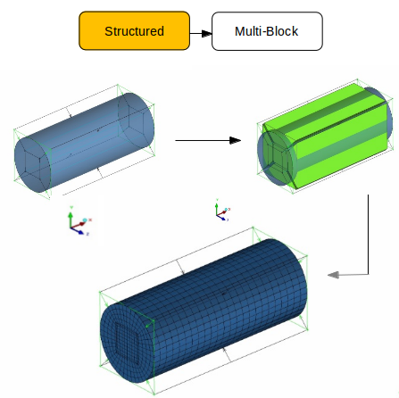 Structured grid generation of a cylinder using multi-blocks
3. Unstructured Grid :
It is the entire discrete cells we generate within the CFD space are randomly spaced & do not follow any single pattern & hence the name un-structured mesh. The types of unstructured mesh are shown in figure below:
Triangular/ Tetrahedron :
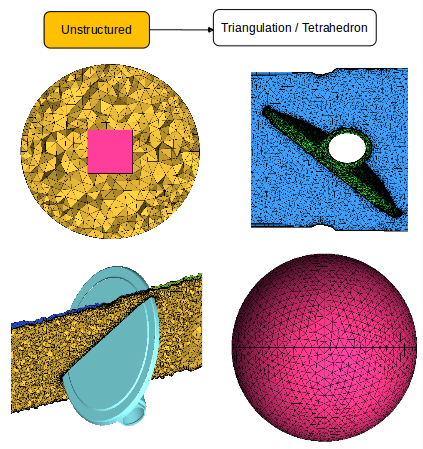
Unstructured grid generation examples using triangular & tetrahedron elements
Quadrilateral/ Hexahedron :
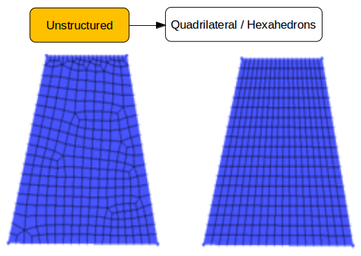
Unstructured grid generation examples using quadrilateral & hexahedron elements
4. Hybrid Grid :
Most of the complex meshing process used to study complex geometries as shown in figure below. The top part of the image has squares and triangles i.e. tetrahedrons & hexahedrons in volume. Since the shape/ geometry is complex we cannot capture the shape profile by using a single element type, hence we use multiple types so we use triangles, prisms, wedges as well as hexahderon. Similarly for volume mesh of a sphere along the sphere surface we use tetrahedron and inside we use hexahedron. Thus combination of different shapes gives us a hybrid mesh.
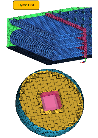
Example of hybrid grid generation with different shape elements
The Author
{module [327]}