Grid Generation for CFD Simulation : Insights with Demo
Knowing about the grid generation process as discussed in our earlier blog, Grid Generation for CFD Simulation: Introduction, we have seen what is a mesh, how a mesh is created using a software, what are mesh types etc. However once a mesh is created the challenge remains to assure that a given mesh is good & would generate accurate results. So there are some terminologies associated with mesh quality & let us know them.
Mesh quality :
As a term "mesh quality" is a combination of various parameters which together decide how appropriate the mesh is, in order to give accurate CFD results, as is well known that a better the mesh quality, better the results.
In general, as a thumb rule compared to a tetrahedral mesh, hexahedral mesh will always give more accurate results because the mesh elements are always aligned with the flow direction, but it is not possible to mesh the entire geometry using hexahedral mesh. Hence what generally is practised is within regions of importance like curved geometry or regions of predominant flow phenomena we make hexahedral mesh/ prism mesh in order to capture flow aligned phenomena and for those regions away or exiting etc, wherein it is not so important to capture the exact flow phenomena that accurately, we can use tetrahedral type of elements. Thus we use mixing of such elements to generate our mesh which is also having accurate results without having large amount of mesh elements.
For judging the quality of mesh we have three criterion:
- Mesh skewness: It is a qualitative or quantitative parameter that decides whether the mesh is having a large amount of skewness or it is an ideal triangle or a square.
- Mesh smoothness: It describes as to how smooth the mesh is, how is its transition whether it is an abrupt or in a smooth manner.
- Mesh aspect ratio: It is the ratio of the largest dimensional length of an element to the smallest length.
Let us understand them further.
Mesh Skewness :
This determines how much the mesh cell/ elements differ from an ideal mesh cell or element. So if we take the case of a 2-D analysis, than an ideal mesh element will be a square & a triangle i.e. an equilateral triangle and in case of 3-dimensional analysis it will be a cube when using hexahedron and for a tetrahedron will be a perfect equilateral tetrahedron.
For a hexahedron element, skewness is obtained as follows :
For each of 6 faces the angle between the face normal & the vector which is defined by the centre of the hexahedron and the centre of the face will be calculated.
The maximum value thus obtained is normalized so that "0" corresponds to a bad element with high skewness and "1" corresponds to a perfect cube. This is the mathematical method for calculating the skewness but in short it means how closely the element is close to the cube. So for the case with a perfect cube it will be "1" & if its deviating from it by a large amount it will be near to "0".
For Triangular elements, skewness is obtained as follows :
Skewness is defined as the ratio of area of element & area of an ideal equilateral triangle. For a quadrilateral element skewness is defined/ obtained by connecting the mid-points of each side with mid-points of opposite side and finding the angle between them.
Within software the calculation is a mathematical process, but in short by definition skewness means how close our element is to the ideal element.
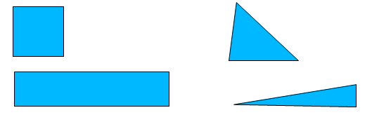
Mesh Aspect Ratio :
It is the ratio of the longest edge length to the shortest edge length. As in figureit shows a perfect aspect ratio (one in ideal situation), but if we stretch the square the longest edge becomes very large compared to the shortest edge. So the aspect ratio is increasing and that means that it may not give the best accurate results. Also for a triangle an equilateral triangle has the perfect aspect ratio, but as we stretch, it will give a bad aspect ratio.
 For Quadrilateral : The vector for each 4 quadrilateral nodes form a parallelogram. The area of each parallelogram is divided by each component vector to give 8 possible aspect ratios & the minimum of this aspect ratio is taken as aspect ratio for quadrilateral element.
For Hexahedral : It is defined by the size of minimum element edge divided by the size of maximum edge.
For Tri & Tetra : ANSYS ICEM CFD does it by calculating the ratio between the radii of an inscribed sphere to a circumscribed sphere for each element.
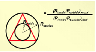
For triangular elements, this generation is done using circles & for tetrahedron elements with spheres.
These values are scaled so that an aspect ratio of "1" is perfectly regular, & an aspect ratio of "0" indicates that the element has zero volume. So as in the figure above, if the triangle is stretched too much it will end-up with zero volume & thereby forming the worst cell/ element.
Mesh Smoothness :
It determines how the size of the mesh element is changing; because within the entire CFD space we cannot have elements having a single size. We have to change the size in order to control our CFD domain mesh count. Hence we use different size of mesh elements in order to fill the space.
So a smooth mesh size change means, that the element adjusts to a particular cell must have a size, that is equivalent or approximately increasingly by a ratio of 1.2 or 20%.
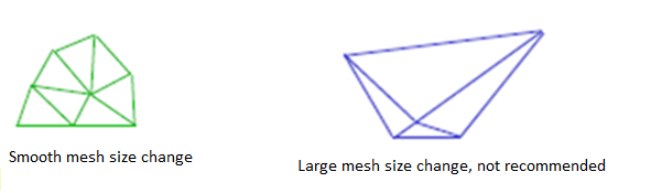
Whereas in the image above this triangle is very large compared to small triangle; (>20%) hence the cell size is changing abruptly and not a smooth change/ transition. A smooth transition is required to capture the change of CFD results, hence we need to make sure that there is always a smooth transition.
Mesh Density :
It means as to how closely or coarsely mesh elements are packed or placed. As we have to vary the mesh size in the different regions of CFD space, for example in regions where the flow is very close to wall, we have to define mesh so that the triangle and quadrilateral and other shapes are packed together closely in order to capture the boundary layer, but away from the walls/ surfaces we can have elements that are larger or coarsely spaced.
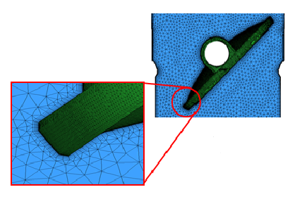
You can see in figure that near the surface we have defined fine mesh, but away from it we have a coarse mesh. This change from a closely packed mesh to a coarse mesh is called change in mesh density.
In regions of flow gradients the mesh density should be high enough to capture all the flow variables or changes. However for regions away from walls, where the flow gradients are not present we can have low mesh density i.e. a coarse mesh.
Meshing guidelines :
To summarize the best practices for meshing can be as follows:
- Important flow features should be resolved
- Cell aspect ratio should be near one where flow is multi-dimensional
- Change in cell/element size should be smooth
- Ideally change in grid spacing should be around 1.2 times
- More the cell count higher the accuracy but more CPU time to solve
However the cell counts can be limited without sacrificing on the accuracy using a non-uniform grid , with varying mesh density and prism layer/ boundary layer mesh.
|
{modal index.php/en/?option=com_content&view=article&id=119}
{/modal}
{modal index.php/en/?option=com_content&view=article&id=119}
 {/modal} {/modal} |
Blog Co-Author:

Ganesh Visavale
Co-Founder & General Manager,
LearnCAx
Inspire | Educate | Mentor
![]()
![]()
![]()
![]()
Website: LearnCAx.com | Email: ganesh@cctech.co.in
The Author
{module [327]}